
Sewage Treatment Plant Design: A Complete Guide
From population and flow to tank sizing, sludge handling and pumps: how an STP is designed.
Quick Answer
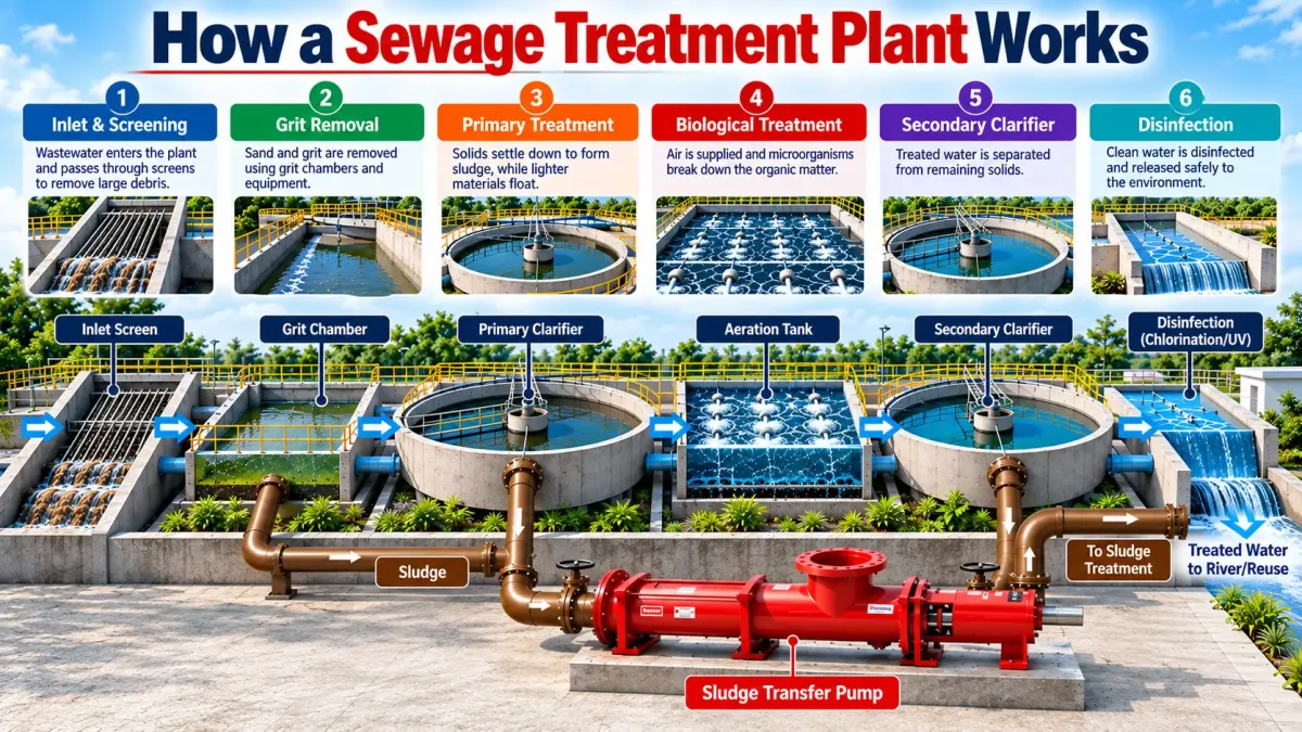
Sewage treatment plant design starts with estimating the daily sewage flow and its strength (BOD, COD, TSS), then fixing the treated water quality required. Engineers apply a peak factor, choose a treatment technology, size each unit from standard design parameters, plan sludge handling and select pumps and blowers for every duty. In India, the CPHEEO Manual on Sewerage and Sewage Treatment is the main reference.
On This Page
- Step 1: Collect the Sewage Treatment Plant Design Inputs
- Step 2: Calculate Average and Peak Flow
- Step 3: Define Raw and Treated Water Quality
- Step 4: Select the Treatment Technology
- Step 5: Size Each Treatment Unit
- Step 6: Calculate Air Requirement and Blowers
- Step 7: Plan Sludge Handling
- Step 8: Hydraulic Profile and Pump Selection
- Step 9: Layout, Access and Safety
- Common Sewage Treatment Plant Design Mistakes
- Worked Sewage Treatment Plant Design Example: 200 KLD MBBR
- Estimating Sludge Production
- Instrumentation and Automation
- Designing for Low Energy Use
- Design Review Checklist for Owners
- Frequently Asked Questions
Good sewage treatment plant design is the difference between a plant that quietly meets its norms for twenty years and one that smells, foams and fails inspections. Most STP problems seen in the field, from undersized tanks to clogged sludge lines, can be traced back to design shortcuts.
This guide walks through the STP design process step by step. It is meant for project engineers, consultants, builders and plant owners who want to understand how a plant is sized and what to check in a design. Detailed design should always be done or verified by a qualified wastewater engineer.
Step 1: Collect the Sewage Treatment Plant Design Inputs
Every sewage treatment plant design rests on a few basic inputs. Getting them right matters more than any later calculation.
Key design inputs:
- Population or user count: residents, staff, visitors, beds or rooms
- Water supply rate: often 135 LPCD for urban residential use per the CPHEEO manual, lower for offices and schools
- Sewage factor: typically about 80% of water supply
- Raw sewage quality: BOD, COD, TSS, oil and grease, ideally from lab tests
- Treated water quality: discharge norms or reuse standards
- Site constraints: available area, depth, groundwater level and access
Step 2: Calculate Average and Peak Flow
Average flow is calculated as: Population × LPCD × sewage factor. For example, 2,000 people × 135 L × 0.8 = 216,000 L/day, or 216 KLD.
Sewage does not arrive evenly through the day, so units that handle instantaneous flow must be sized for peak flow. The CPHEEO manual gives peak factors that fall as population grows:
| Contributing Population | Peak Factor |
|---|---|
| Up to 20,000 | 3.0 |
| 20,001 – 50,000 | 2.5 |
| 50,001 – 7,50,000 | 2.25 |
| Above 7,50,000 | 2.0 |
Screens, grit chambers, raw sewage pumps and pipelines are sized on peak flow. The equalization tank then evens out the flow so the biological units can be sized closer to average flow.
Step 3: Define Raw and Treated Water Quality
Typical Indian domestic sewage has BOD in the range of roughly 150–300 mg/L, COD around 300–600 mg/L and TSS around 200–400 mg/L, but hotels, hospitals and food courts can be much stronger. The treated water target is set by your consent conditions. Our article on CPCB STP norms lists the current discharge standards. Reuse for flushing or cooling usually needs tertiary treatment on top.
Step 4: Select the Treatment Technology
In sewage treatment plant design, technology selection balances footprint, power, outlet quality, capital cost and operator skill. MBBR is popular for compact sites, SBR for variable flows and nutrient removal, MBR for high-quality reuse in tight spaces, and extended aeration where land is available. Our MBBR vs SBR vs MBR comparison explains the choice. For small capacities, a factory-built packaged STP may be the most practical route.
Step 5: Size Each Treatment Unit
Each unit is sized from flow, load and accepted design parameters. The values below are typical ranges used in practice; the final values depend on technology, sewage strength and the governing manual.
| Unit | Key Design Basis | Typical Range |
|---|---|---|
| Bar screen | Clear spacing, approach velocity | Fine screens 6–10 mm; velocity about 0.6–1.0 m/s |
| Equalization tank | Hydraulic retention time | About 4–8 hours of average flow |
| Aeration tank (extended aeration) | HRT, MLSS, F/M ratio | HRT about 16–24 h; MLSS 3,000–4,000 mg/L |
| MBBR reactor | Media fill and surface area loading | Media fill about 30–60% of tank volume |
| Dissolved oxygen | DO in aeration tank | About 1.5–2.0 mg/L |
| Secondary clarifier / tube settler | Surface overflow rate | Clarifier about 15–25 m³/m²/day; tube settlers higher |
| Chlorine contact tank | Contact time | At least 30 minutes |
| Pressure sand / carbon filter | Filtration rate | Sized on flow with backwash provision |
Important: These figures are indicative and for understanding only. Final sewage treatment plant design must follow the CPHEEO manual, your SPCB conditions and the technology supplier’s process design.
Step 6: Calculate Air Requirement and Blowers
Bacteria need oxygen to break down organic matter. Engineers calculate the oxygen demand from the BOD load to be removed (plus nitrification, if required), convert it to an air requirement using the diffuser transfer efficiency, and select blowers with a working and standby unit. Blowers are usually the largest power consumer, so efficient blowers and VFD or DO-based control pay back quickly.
Step 7: Plan Sludge Handling
Every biological STP produces excess sludge, and many plants fail because sludge handling was underdesigned. The design should cover:
- Return activated sludge (RAS): pumped back to the aeration tank to maintain MLSS.
- Waste activated sludge (WAS): removed to a sludge holding tank or thickener.
- Dewatering: filter press, screw press, centrifuge or drying beds, with polymer dosing.
- Cake handling and disposal: storage, transport and approved disposal route.
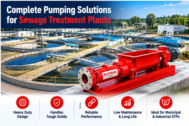
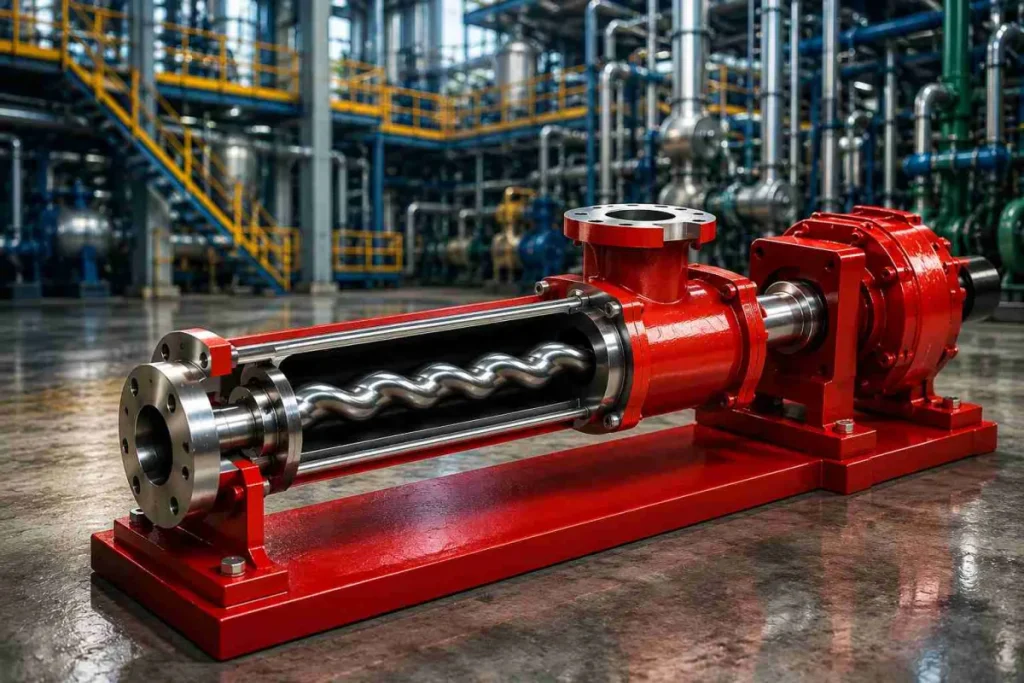
Sludge lines need pumps that tolerate high solids without clogging. A progressive cavity pump is the standard choice for RAS, WAS and filter press feed, while a wide throat pump moves dewatered cake.
Step 8: Hydraulic Profile and Pump Selection
The hydraulic profile shows the water level in every unit from inlet to outlet. Where gravity flow is not possible, pumps are added. For each pump, the designer must define the media, flow, total head, solids content, operating hours and standby arrangement.
Raw Sewage and Transfer
Non-clog submersible pumps lift sewage into the plant and from the equalization tank.
Sludge Duties
Progressive cavity pumps for RAS, WAS, thickened sludge and filter press feed at steady, controllable flow.
Chemical Dosing
Dosing pumps for chlorine, polymer and, where needed, alum or lime.
Tertiary and Reuse
Centrifugal pumps for filter feed, backwash and treated water transfer.
Our complete STP pump guide explains each pumping duty in detail.
Step 9: Layout, Access and Safety
- Arrange units in process order to keep pipe runs short and gravity flow where possible.
- Provide walkways, handrails, ladders and lifting arrangements for pumps and blowers.
- Ventilate covered and basement plants; plan for hydrogen sulphide and confined-space safety.
- Keep space for future expansion and a second treatment stream.
- Provide flow meters, sampling points and an operator room with a lab corner.
Design for the operator. If equipment cannot be reached, lifted out or cleaned easily, it will not be maintained.
Common Sewage Treatment Plant Design Mistakes
- Guessing raw sewage strength instead of testing it
- Ignoring peak flow when sizing screens and pumps
- No standby blowers or pumps
- Undersized sludge handling and dewatering
- Choosing impeller pumps for thick sludge, leading to clogging
- No access for maintenance in basement plants
- Designing for full occupancy only, with no plan for low initial loads
For cost implications of design choices, see our sewage treatment plant cost guide. For more background on unit processes, see sewage treatment. Ropman Engineering Corporation supports consultants and EPC contractors with pump sizing for STP sludge and dosing duties, with pumps built in Meerut, India.
Worked Sewage Treatment Plant Design Example: 200 KLD MBBR
To see how the steps come together, here is a simplified sewage treatment plant design walk-through for a township of about 1,850 people. The numbers are illustrative and rounded; a real design would be checked against the CPHEEO manual and the supplier’s process calculations.
| Design Step | Illustrative Value |
|---|---|
| Population × LPCD × sewage factor | 1,850 × 135 × 0.8 ≈ 200 KLD |
| Average flow per hour | 200 ÷ 24 ≈ 8.3 m³/h |
| Peak factor (population under 20,000) | 3.0 |
| Peak flow for screens and lift pumps | 8.3 × 3 ≈ 25 m³/h |
| Equalization tank (6 hours of average flow) | About 50 m³ |
| Assumed inlet BOD | 250 mg/L |
| BOD load per day | 200 m³ × 0.25 kg/m³ = 50 kg BOD/day |
| Target treated BOD | Below 10–20 mg/L, per consent |
| Biological stage | MBBR reactor sized from BOD load and media surface area |
| Settler | Tube settler sized on surface overflow rate at average flow |
| Tertiary | Pressure sand filter, activated carbon filter, chlorination |
| Sludge handling | Sludge holding tank, polymer dosing, filter press with progressive cavity feed pump |
Notice how each number leads to the next. The BOD load drives the biological reactor and air demand, the peak flow drives screens and lift pumps, and the expected sludge production drives the holding tank, dewatering unit and sludge pump sizing.
Estimating Sludge Production
Sludge handling is often the most underdesigned part of a plant. As a rough rule, biological processes produce a fraction of a kilogram of dry sludge for every kilogram of BOD removed, with the exact figure depending on the technology and sludge age. Extended aeration and other long sludge age processes produce less sludge, while high-rate processes produce more.
Once dry solids per day are estimated, the designer converts them to a sludge volume using the expected solids concentration. Thin waste sludge at under 1% solids takes up far more volume than thickened sludge at several percent. That volume sets the size of the holding tank, the capacity of the filter press or screw press, and the flow and pressure of the sludge feed pump.
Tip: Design sludge pumps for the thickest sludge they may see, not the average. Sludge that has been held longer than planned is thicker, and an undersized pump is the first thing to fail.
Instrumentation and Automation
Modern sewage treatment plant design includes enough instruments to run the plant efficiently and prove compliance.
Essential
- Inlet and outlet flow meters
- Level switches in sumps and tanks
- Blower and pump run-hour meters
- Pressure gauges on pumps and filters
Recommended
- Online DO sensor with blower VFD control
- pH and turbidity on treated water
- Residual chlorine analyser
- Remote monitoring and alarms
DO-based blower control alone can noticeably reduce power use, because blowers only deliver the air the bacteria need instead of running flat out all day.
Designing for Low Energy Use
- Use fine bubble diffusers with good oxygen transfer efficiency in aeration tanks.
- Select efficient blowers and drive them with VFDs.
- Use gravity flow between units wherever the levels allow.
- Size pumps close to their best efficiency point rather than heavily oversizing them.
- Use progressive cavity pumps on sludge duties, where their efficiency holds up as sludge thickens.
- Recover treated water for reuse to lower the cost of fresh water.
Design Review Checklist for Owners
Even if you are not an engineer, you can review a sewage treatment plant design proposal using these questions.
Ask your consultant or supplier:
- What population, LPCD and sewage factor did you assume, and why?
- What peak factor and inlet BOD, COD and TSS are used?
- Which norms is the treated water guaranteed to meet?
- Are there standby blowers and pumps for every critical duty?
- How much sludge will be produced, and how will it be dewatered and disposed of?
- What type of pump is used for each sludge duty?
- What is the connected and running power load?
- How will the plant run at low initial occupancy?
- How can the plant be expanded later?
- Can every pump, blower and diffuser be accessed and removed for maintenance?
Good answers to these questions are the best sign of a robust design. For running the plant after commissioning, see our STP maintenance checklist.
Frequently Asked Questions
How do you calculate STP capacity?
What is the peak factor in STP design?
What are the main STP design parameters?
Which manual is used for STP design in India?
Which pumps are used in STP design?
How is sludge production estimated in STP design?
What instruments should an STP have?
How can STP design reduce power cost?
Designing an STP? Get Pump Sizing Support
Share your sludge flow, solids content and head, and Ropman will size progressive cavity, wide throat and dosing pumps for your STP design.
Request a Quote